
Assembling The Arms
Maslow4 has a few parts that need to be glued so we will start there so that the glue can begin drying. In all of the cases where we use glue, the glue is not structural, it is just meant to hold parts in place that might move due to vibration. Use just a small amount of glue.
Assembling the arms is the most complex and difficult part of the Maslow4 build process so we’re going to jump right in and start there.
Find any of these steps confusing or get stuck? Don’t forget, you aren’t alone! Maslow is a community driven open source project. Ask in the forums and we’ll figure it out together!
First we will gather the four belts, the four arms, and the super glue which we will need for this step. The top and bottom halves of the arms are identical.
Note: Due to issues shipping glue (a liquid) by air we have started gluing the glued parts at the factory. If you kit has these parts already glued you can skip ahead)
Removing the spool from each arm, place a small drop of super glue in the slot where the belt will attach like this.
A couple notes on this section. The super glue is opened by twisting the top. One end of each belt might fit into the spool more easily than the other so it’s worth checking both ends before starting with the glue.
You do not need to use much glue. A very small drop is fine.
Then press the belt fully into the slot. It should not stick above the top of the slot.
Repeat this step for all four spools.
Next we will glue the encoder magnets into the rollers. For this step we will need to gather the eight rollers and the four magnets.
The four magnets will be stuck to the gears or to the Torx screwdriver
We will just need four of them for this step:
Note that each roller has two ends. One end has a shallow recess to hold the magnet. That is the side we want to use.
Again using a drop of glue place a magnet in the end of each of the four rollers. Note that the magnet will be slightly recessed below the top of the roller.
Be careful, the magnets will try to stick to things while the glue is drying.
The magnet is symmetrical so it can be placed in either orientation.
Now set those aside to dry. Be careful not to put them too close together while drying because the magnets will attract and stick together. You have to place them further apart than you might expect.
Next, we want to install six bolts into one arm half. Be sure to use the bolts without the blue thread locker applied for this step.
The bolts will fit into the arm half like this. Use a non-lock nut to help pull them into place.
Remove the nut once each bolt is in place.
A small socket or nut driver can help here to prevent the nut from spinning.
Next, install six locking nuts in a new arm half.
The process to install the nuts is the revers of the bolts. Place a nut in each opening and then us a bolt from the other side to pull the nut into place.
Remove the bolt once each nut is in place.
When we are done with both halves one half should have only nuts and the other half should have only bolts.
Next, we can start working on assembling the rest of the arm. To do that we’re going to need to collect an arm half, a DC drive motor, and an encoder board.
Next place the encoder board over them. There are two guide pegs which will hold it in just the right place.
Then place the motor over that. The orientation of the motor does not matter.
The bolts which connect the motor to the arm can wiggle themselves loose over time so we’ve included bolts with blue removable thread locker applied to them in your kit.
Collect four of these bolts.
The bolts with blue thread locker will only be used to attach the motors.
And then bolt the drive motor into place.
Community Note: There is some play in how these bolts attach the motor and having the motor further forward (to the right in the picture) is better than further back. If you find that the gears are too tight in later steps you can loosen them up by moving the motor forwards.
Next we need to collect our drive gear (which has a D shaped opening in the center), a set screw, and the T8 torx wrench:
Thread the set screw part way into the drive gear:
Then attach it to the motor shaft. The gear should be almost but not quite touching the plastic or lifted up about the width of an index card or three pieces of paper. Tighten the set screw to lock it in place.
Note that there is no bearing under the drive gear.
Next press three bearings into the three openings in the arm plastic as shown here.
Insert the idler gear (the gear with the shaft built in) into the bearing next to the drive gear.
Next set the half of the arm with the gears aside and we will work on the other half. First we will need to press four bearings into place like this.
Next we will attach the belt guard. Insert three nuts into the holes in the top of the belt guard with the open end of the nuts down.
Then add three bolts from the other side to hold it in place.
Note that the bolts are too short to fully engage the locknuts here.
If you have issues with your belt guard rubbing against your drive gear, loosening these three bolts slightly will allow you to adjust it’s position.
Next we need to wait for the glue to finish drying on our other parts before we can proceed. Feel free to repeat the steps up to this point for all four arms. If you feel like continuing to work on other parts of the machine while the glue is drying you can start on the Assembling the Sled section.
This next part where everything comes together sort of happens all at once and can be a little tricky. Don’t feel frustrated if it takes a couple of tries to get it right. With practice it can be pretty smooth, but the only way to get the hang of it is to try.
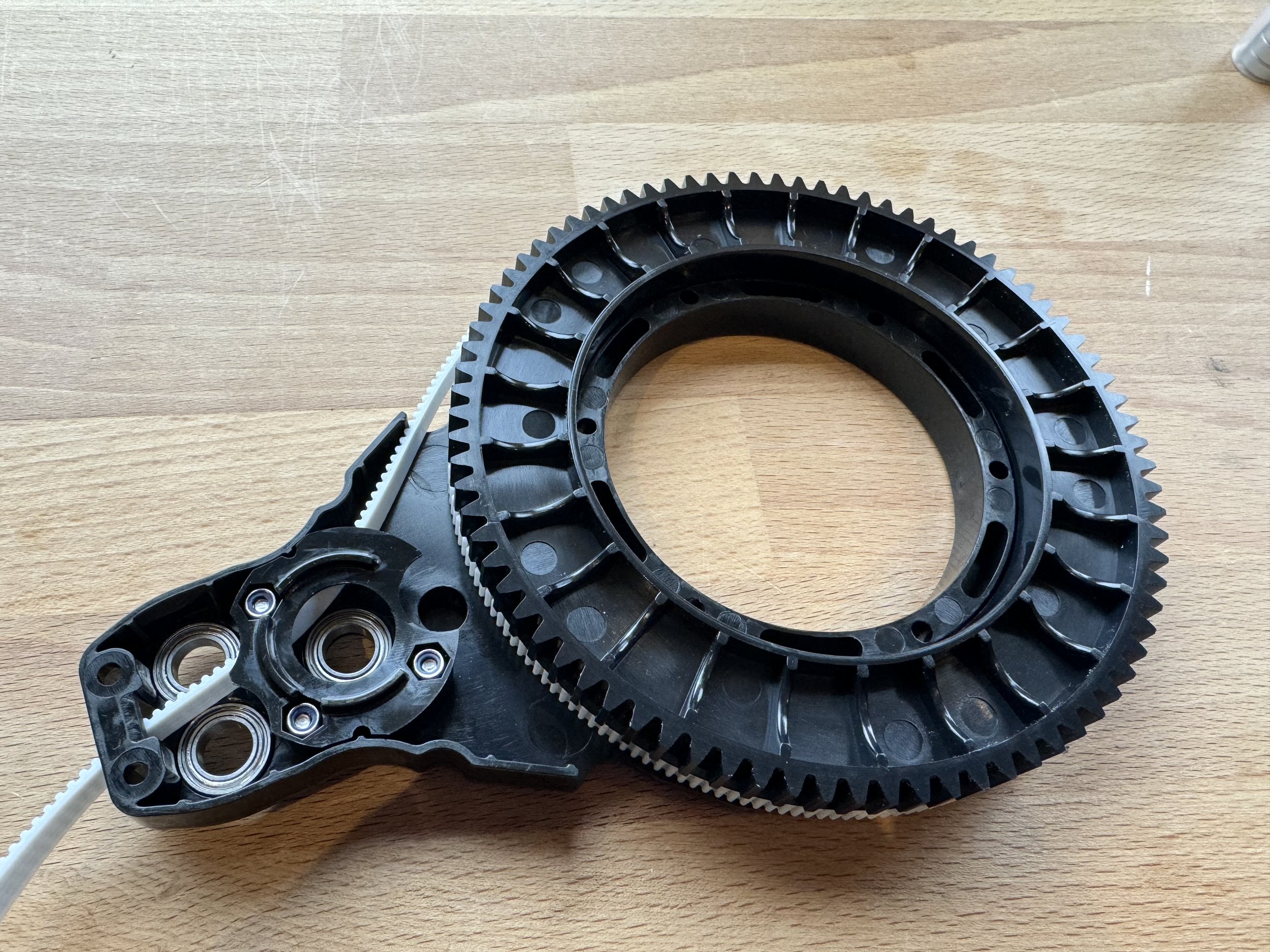
Feed the free end of the belt from the spool (belt side down, gear side up) through the belt guard.
Place the spool onto the arm.
Insert the two rollers.
Note that one roller has a magnet and the other does not. The placement of the magnet is very important. It must line up with the sensor (in green on the right) on the other half of the arm when the two halves come together.
Line up the two arm halves and then press the two halves together. This is much easier said than done and this is the trickiest step of the build process.
Generally I start from the back of the arm (the side that doesn’t have the belt coming out of it) and work my way forward.
There are three things which will need to go into place. First the idler shaft needs to align with the hole on the opposite side. Then the drive shaft needs to align with the opening in the bearing on the bottom, then the rollers will need to line up with bearings on the other half.
I find that by checking each one of these locations in turn and getting them lined up the two halves will come together. It can be helpful to use the allen wrench to jostle the rollers around to make them line up.
Then we join the two halves together with eight bolts.
Six of the bolts are the bolts we placed early on in the assembly process. The remaining two bolts are close to the front.
Finally we need to attach the belt end to the end of our arms. Gather the eight belt end parts:
Then take two of the belt ends and the end of one of the belts extending from our arms:
Fold the belt over and press it into the slot in the belt end so that the end protrudes only slightly. This can be tricky to do because the fit is tight (it needs to be tight to handle the force). I find that starting with the loop in the belt at the open end of the slot and pushing it forward works well. You can use the torx wrench to lever it into place. Watching the video at the top of this page can help.
Then press on the other half of the belt end.
And secure it with a bolt and non-lock nut.
Congratulations! You are done with the most difficult and longest part of the assembly process!
Next lets assemble the sled.